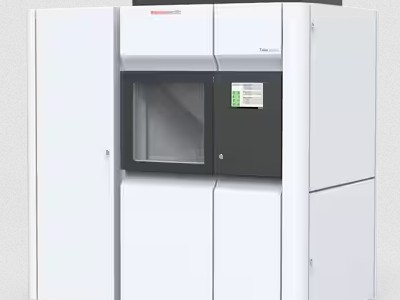
Arctica Talos
Documentation for the Thermo-Fisher Talos Arctica 200 kV Microscope
The Thermo-Fisher Talos Arctica is a 200 kV scanning and transmission electron microscope (S/TEM)
Source: Field Emission Gun (XFEG)
Voltage: Up to 200 kV
Wavelength: 2.51 pm
Sample Holder: Autoloader, 12 samples
Cryo: Yes
Cameras
1. Ceta-16Sensor Type:Hybrid CCD
Pixel Size:14μm
Sensor Size:4k x 4k
Sensor Type: CMOS
Pixel Size: 5 μm
Sensor Size: 5760 x 4092
SerialEM
Gatan Microscopy Suite
The Talos Arctica is a dual-condenser lens microscope. That means that parallel illumination only occurs at a static C2 intensity per spot size. Below is a table of spot sizes, and their corresponding C2 intensity needed for parallel illumination:
Gun Lens 3.6
| Spot Size | C2 |
|
1 |
46.78 |
| 2 | 45.23 |
| 3 | 43.35 |
| 4 | 42.27 |
| 5 | 41.20 |
| 6 | 39.78 |
| 7 | 38.22 |
| 8 | 37.62 |
| 9 | 37.00 |
| 10 | NA |
| 11 | NA |
Gun Lens 4
| Spot Size | C2 |
|
1 |
46.8% |
| 2 | 45.6% |
| 3 | 43.9% |
| 4 | 42.3% |
| 5 | 41.1% |
| 6 | 39.6% |
| 7 | 38.6% |
| 8 | 37.3% |
| 9 | 36.9% |
| 10 | NA |
| 11 | NA |
Sensor Type: CMOS
Pixel Size: 5 μm
Sensor Size: 5760 x 4092 (Normal), 11520x8184 (Super Resolution)
Peak DQE: 15.04 e-/physical pixel (Normal), 7.502 (CDS)
The Gatan K3 camera has several modes of operation, many of which can be combined. The two major detection modes are:
- Linear Mode
- Counting Mode
Typically, counting mode is recommended unless contrast and pixel saturation are an issue.
Additionally, the K3 may operate in either:
- Standard resolution (5760x4092)
- Super resolution" (SR) mode (11520x8184)
Super resolution mode quadruples the number of pixels by essentially triangulating electron impact events in a pixel to determine the quadrant of the pixel that the electron hit.
Additionally, the recording rate and baseline noise is impacted by two different recording modes:
- Normal (1500 frames-per-second)
- Correlated-Double-Sampling (CDS) (760 frames-per-second)
Gatan claims that "The addition of correlated double sampling mode (CDS) now boosts the DQE even higher to provide the ultimate in data quality". Essentially, CDS mode reads each frame twice: once to establish baseline noise levels, and the next to record the data.
Listed here is a magnification table to help determine appropriate magnification and other optimal settings for single particle data collection.
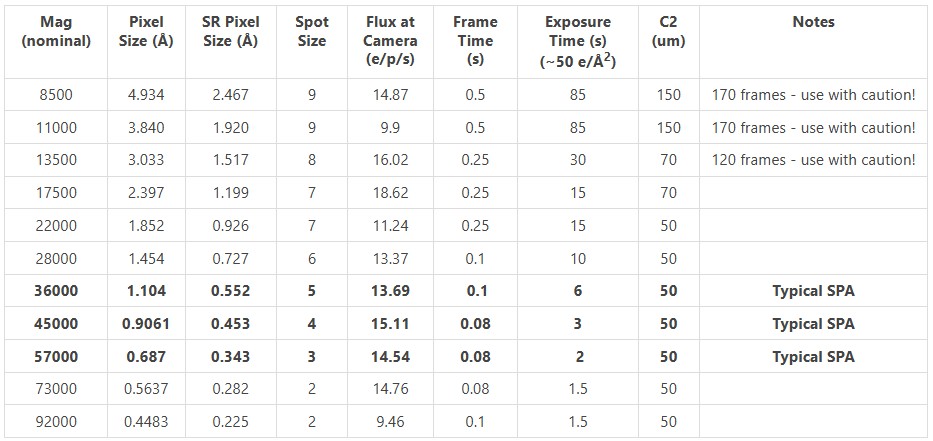
All values for gun lens 3.7.
Considerations for Data Collection
A number of variables must be considered for each data collection. Follow this guide for single particle data collection optimization:
- Choose a magnification.
- The first consideration for selecting a magnification is the pixel size. The pixel
size should ideally be:
target resolution / 3, or smaller.- Super-resolution (SR) mode halves the pixel size, but is less effective at higher magnifications.
- The second consideration for selecting a magnification is field-of-view (FOV) vs detector quantum efficiency (DQE). At low magnification, FOV is larger, meaning that more particles are collected per-image. At high magnification, DQE is higher, meaning the quality of the data collected is greater.
- Data collection speed. Exposure times are shorter at higher magnification, but FOV is smaller, so each exposure contains fewer particles.
- The first consideration for selecting a magnification is the pixel size. The pixel
size should ideally be:
- Adjust exposure and frame times.
- Take a Record of an empty hole, and check the dose on the camera. It should be close to what is listed here. Calibrate SerialEM with that dose, so that you know what the dose on the sample will be.
- Take a Record of a sample with typical ice thickness. See how much dose is lost due to the ice.
- Adjust your exposure time (in seconds) to target the dose on the sample that you want, based on the camera dose at the empty hole.
- Adjust your frame time (in fractions of a second) to target ~0.8 e/p/s, based on the
camera dose of the sample with ice.
- In general, you want as few electrons per-pixel per-frame as possible, while still being able to align the frames. This number tends to be ~0.8 e/p/s.
- Be sure to consider how many frames you are writing, and how large the files will be. More frames will result in larger files that use more disk space and take longer to move and process.
Below is the modulation transfer function for the Gatan K3 camera:
Save the followings in text document, and rename the file "k3-200kv.star" to make it compatible for RELION:
data_mtf_k3_std_200kv
loop_
_rlnResolutionInversePixel
_rlnMtfValue
0.000000000 1.000000000
0.015873016 0.992006436
0.031746032 0.984482532
0.047619047 0.977220107
0.063492064 0.970036615
0.07936508 0.96277324
0.095238095 0.955293437
0.111111111 0.947481509
0.126984127 0.939241219
0.142857143 0.930494442
0.158730159 0.921179852
0.174603175 0.911251641
0.190476191 0.900678283
0.206349207 0.889441327
0.222222222 0.877534229
0.238095238 0.864961225
0.253968254 0.851736231
0.26984127 0.837881788
0.285714286 0.823428039
0.301587302 0.808411746
0.317460318 0.792875339
0.333333334 0.776866005
0.349206349 0.760434809
0.365079365 0.743635861
0.380952381 0.726525508
0.396825397 0.70916157
0.412698413 0.69160261
0.428571429 0.67390724
0.444444445 0.656133466
0.460317461 0.638338062
0.476190476 0.620575997
0.492063492 0.602899875
0.507936508 0.585359435
The Gatan K3 has a complicated gain recording and correction process. This page will detail them.
Gains are recorded and stored in the folder C:\ProgramData\Gatan\Reference Images in Digital Micrograph .dm4 format. The gain names correspond to:
- .m0
- Linear, non-CDS
- .m1
- Counted, non-CDS
- .m2
- Linear, CDS
- .m3
- Counted, CDS
- .m4
- User gain (if in-use)
When using SerialEM with gain correction, gains will not need to be separately saved and applied afterwards. SerialEM will automatically find and import the necessary gains, unless they simply do not exist.
If recording in SerialEM without gain correction enabled, SerialEM will copy the gain file to the directory that it saves the frames to.
Gain references should be taken every time after the sensor is annealed. Gatan recommends that dark references should be taken every 24 hours, or as needed as static charge builds up on the sensor. We have found 6 hours to be the preferred time to take new dark references during data collection.
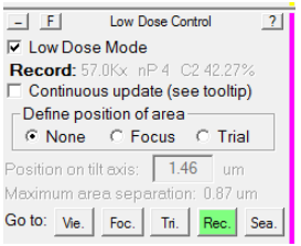
Typically, it is desirable to have a larger defocus when in View mode than in record mode, to make objects more visible at low magnification. Typically, this defocus offset is approximately -50 microns. However, sometimes due to SerialEM bugs or glitches, this offset sometimes doubles -100 microns. This can drastically affect your View-Record alignment. To reset it, follow this procedure:
- In the Low Dose control panel, make sure you load the Record view mode:
- Using the Microscope Control panel, set the defocus in record mode to 0:
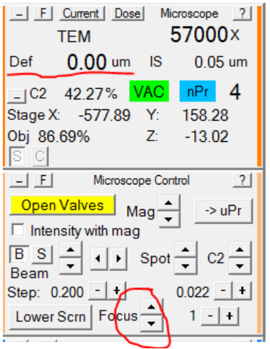
- Load View mode, and set the defocus offset to 0:
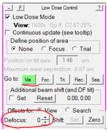
- In the Microscope Control panel, set the microscope defocus to 0:
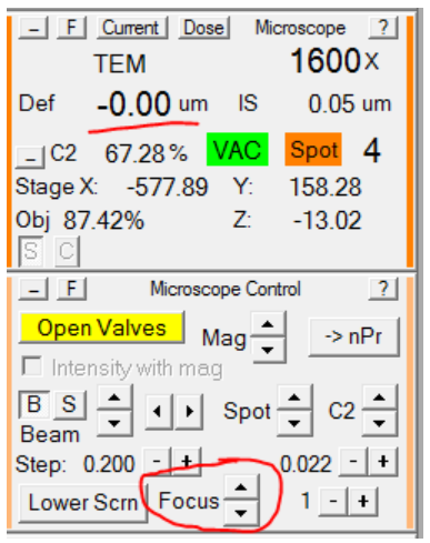
- In the Low Dose Control panel, re-load Record mode, and set the Defocus Offset back to -50:
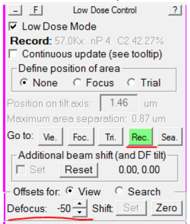
- Re-load View mode, and verify that the microscope defocus is now -50:
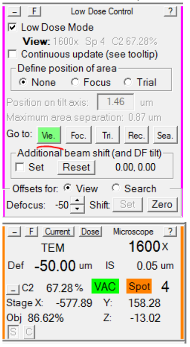
Because View mode is typically a much lower magnification, and an entirely different FEG-probe mode than Record, sometimes, where you center in View is not actually what gets imaged in Record. Additionally, a high defocus offset in View mode can cause further drift. If View and Record are not aligned, the first thing you should do is check that the View mode defodcus offset is correct.If it is correct, or if you have intentionally changed it, but View and Record are still not aligned, follow the procedure below to re-align them:
- Find and center (via right-mouse click and drag) an object in either Record or Preview mode that is large enough to see from View mode as well. (Hint: Preview mode behaves like Record but without saving/aligning frames, and is typically a shorter exposure). Here, I
am using the corner of a square of ice:
As you can see, I have right-clicked and dragged the crosshair to be centered over the corner. It's a good idea to take a second image after you have centered, to verify that the centering worked.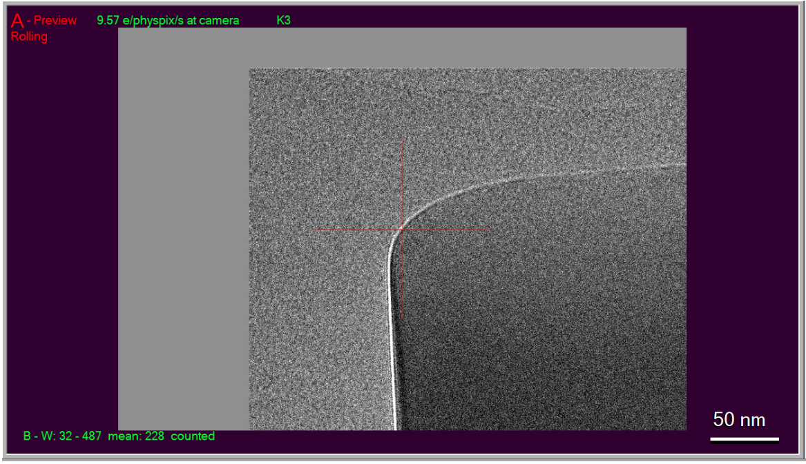
- Take a View image and see where the crosshair goes:
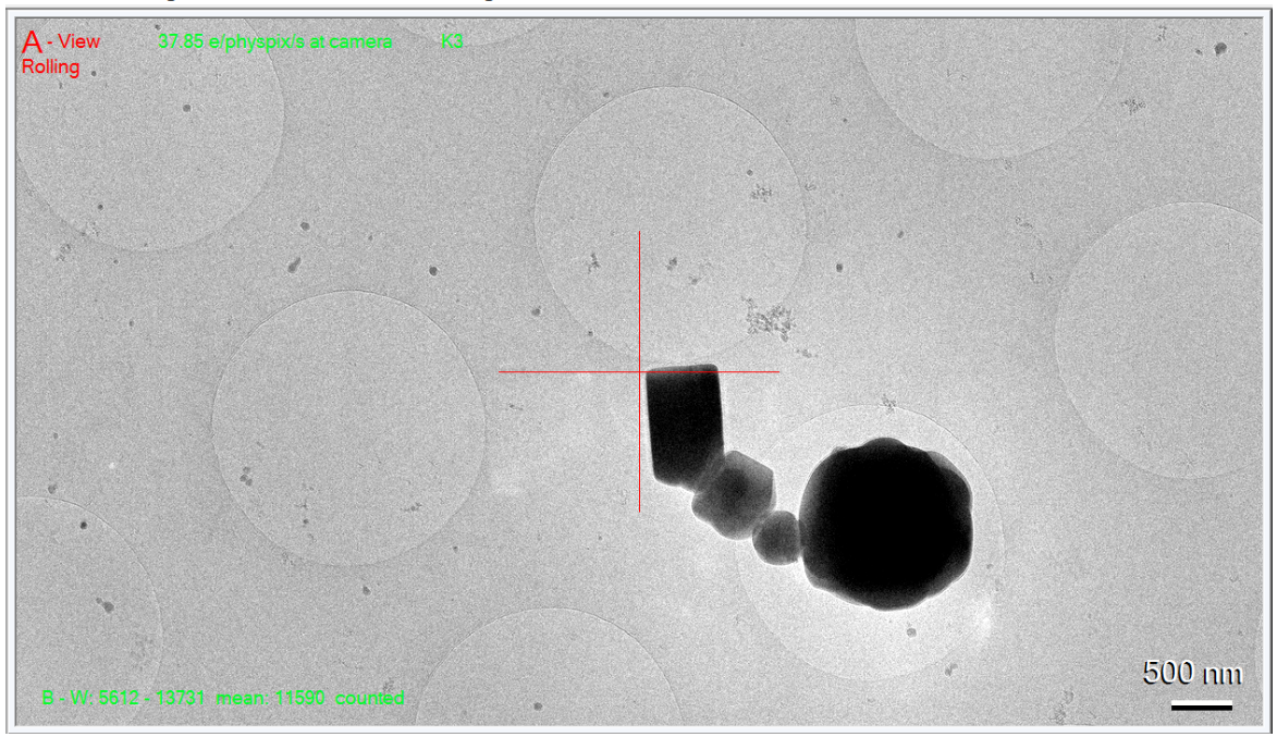
Here you can see it's close, but not perfect. - Right-click and drag the mouse to center the crosshair over the object you centered
in Record:
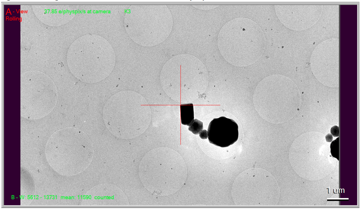
- In the Low Dose Control panel, select Shift: Set:
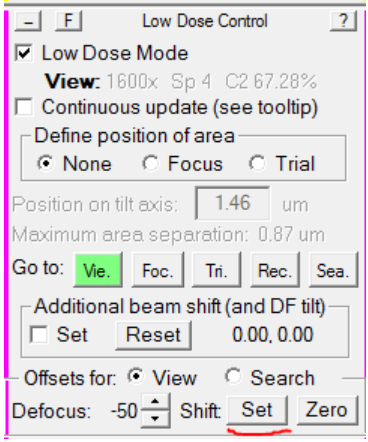
SerialEM will take a new View image. The crosshair should now be centered over the same area it was when you centered the camera in Record. If not, repeat step 4 until it is. - Find a new object in View mode, center it in View mode, and take a Record or Preview. The Record should now be centered (or very close) where your crosshairs were in View mode.
Typically, people use the microscope PC to load or change cartridges, because it is more direct. shows you more of what's happening re: vacuum status, arm motions, etc, but if you are operating the microscope remotely, you may wish to do this via SerialEM.
To load a cartridge, simply open the Scripts menu at the top, and select Edit/Run One Line. A dialog box will open with 5 lines. There may or may not be something in each line.
You can simply delete what is present in one of the lines, and enter LoadCartridge n where n is the cartridge number you wish to load. Then click Run. In the bottom right, SerialEM will tell you it is doing a Long Operation of loading a cartridge. When that finishes, the cartridge is loaded.


